Hold down the T key for 3 seconds to activate the audio accessibility mode, at which point you can click the K key to pause and resume audio. Useful for the Check Your Understanding and See Answers.
Lesson 3: Molecular Shape
Part a: Valence Shell Electron Pair Repulsion Theory (VSEPR)
Part 3a: Valence Shell Electron Pair Repulsion Theory (VSEPR)
Part 3b:
Advanced VSEPR
Part 3c:
Molecular Polarity
Part 3d:
Hybridized Orbital Theory
What is Molecular Shape?
 Molecular shape refers to the general three-dimensional shape assumed by the atoms of a molecule. It describes how the terminal atoms bonded to the central atom spread out in space to form a particular geometry. Descriptions of a molecule’s shape will utilize geometric-sounding names like linear, trigonal planar, tetrahedral, octahedral, trigonal bipyramidal, and more. The descriptions may also include information about the angle formed by the bonds holding atoms together in the molecule. Two bonds may be described as making a 109.5° angle, a 120° angle, or a 180° angle, etc.
The shape that a molecule assumes is an important attribute that affects the functionality of the substance. Shape affects whether a substance will dissolve in water or other solvents. Shape affects the tendency to react. Shape even affects whether the substance is a solid, liquid, or a gas. Designers of pharmaceuticals must give keen attention to a molecule’s shape. It’s ability to bind to a particular biological site is dependent upon its shape. In Lesson 3, we will learn about the principles that allow chemists to predict the molecular shape of compounds.
Electron Pair Repulsions
 The model used to predict the shape of a molecule is known as the Valence Shell Electron Pair Repulsion Theory (often remembered by the acronym VSEPR). The model presumes that the groupings of electrons surrounding the central atom will repel each other. To minimize repulsions, these electron groups will spread out in the three-dimensional space surrounding the central atom. Repulsive forces decrease with increasing separation distance. So, the repelling groups of electrons assume locations in the space surrounding the central atom that are as far apart as possible.
Electron Pair Geometries
The repulsion of electron groups results in specific geometries that depend upon the number of electron groupings. We will describe each geometry in words and provide a few visual representations. Use the words, the visuals, and your spatial reasoning abilities to make sense of the ideas. Always keep in mind that these geometries are the result of groupings of electrons surrounding the central atom undergoing repulsions and spatial separations.

The two electron pairs surrounding the central atom are acting as two repelling electron groups. Two electron groups will spread out on opposite sides of the central atom to maximize their spatial separation and minimize their repulsions. The electron groups form a linear geometry. A in the diagram represents the central atom. It lies along the line at or near the midpoint.
 The three electron pairs surrounding the central atom are acting as three repelling electron groups. Three electron groups around a central atom will spread out in a plane at 120° angles between them. (The angle measure results from dividing the 360° circular space into three equal sections.) The three groups form a triangle with the central atom A at its center. The electron groups are said to form a trigonal planar geometry.
NOTE: These are two-dimensional diagrams. In an attempt to represent the three-dimensional spatial relationship between the electron pairs and the central atom, the diagrams use solid lines, dashed lines, and wedged lines. A solid line can be perceived  as being located in the plane of the screen. A wedged line comes out towards the viewer in front of the screen. A dashed line is extending into the space behind the screen away from the viewer.
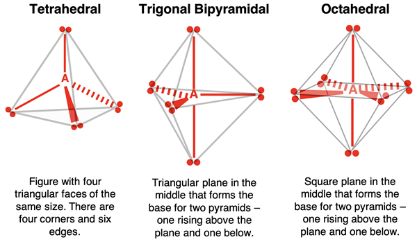
The four electron pairs surrounding the central atom are acting as four repelling electron groups. Four electron groups around a central atom will not occupy the same plane. Instead, they will spread out in the three-dimensional space to form a tetrahedral geometry. A tetrahedron is a four-sided figure with each side having the same length. The central atom is located at the center of the tetrahedron.
 The five electron pairs surrounding the central atom are acting as five repelling electron groups. Five electron groups around a central atom will spread out in three-dimensional space to form a trigonal bipyramidal geometry. Dissecting the name leads to insight on the shape. Three electron pairs form a triangular plane. The central atom A is at the center of this triangle. There is a fourth electron pair above the plane (above A) and a fifth electron pair below the plane the same distance away. These fourth and fifth electron pairs result in the formation of two pyramids – one from the triangular plane up to the electron pair above it and the second from the triangular plane down to the electron pair below it.
 The six electron pairs surrounding the central atom are acting as six repelling electron groups. Six electron groups around a central atom will spread out in the three-dimensional space to form an octahedral geometry. You can envision this shape by picturing four electron pairs forming a square plane. The central atom A is at the center of this square. There is a fifth electron pair above the plane (directly above A) and a sixth electron pair below the plane (directly below A the same distance away. These fifth and sixth electron pairs result in the formation of two pyramids – one from the square plane to the electron pair above it and the second from the square plane to the electron pair below it.
The linear (1-dimensional) and trigonal planar (2-dimensional) geometries are significantly easier to visualize than the other three geometries. The three 3-dimensional geometries are described in the following graphic.
Electron Pair Geometry vs. Molecular Geometry
The electron pair geometries described above refer to how the electron pairs (or groups) surrounding the central atom arrange themselves in the space surrounding the central atom. Keep in mind that not every electron pair is a bonding pair. Some electron pairs are lone pairs not involved in bonding a terminal atom to the central atom. Compare nitrogen trihydride (NH3, a.k.a., ammonia) to carbon tetrahydride (CH4, a.k.a., methane).
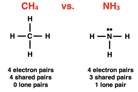
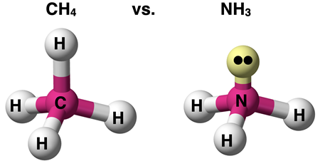
Both molecules have four electron pairs surrounding the central atom that act as repelling groups. Thus, they each have a tetrahedral electron pair geometry. For NH3, only three of those electron pairs are bonding a terminal atom to the central atom. The fourth electron pair is a lone pair. For CH4, all four electron pairs bond a terminal atom to the central atom.
Molecular shape is synonymous with molecular geometry. It describes the shapes that are formed by the terminal atoms that attach to the central atom. When all electron pairs on the central atom are involved in bonding, then the electron pair geometry and the molecular geometry are the same. But when one or more of the electron pairs are lone pairs (unshared pairs), the molecular geometry will be different than the electron pair geometry.
Determining the electron pair geometry and the molecular geometry (shape) requires that a Lewis electron dot diagram be drawn. Decisions regarding these geometries cannot be made without one. There are no good short cuts. Any success identifying geometries without being mindful of the electron dot diagram can be attributed to luck. Relying on luck does not always make for great odds on test day; and it is definitely more associated with naivete and ignorance than education and understanding. (Review Lewis electron dot diagrams.)
For many students, VSEPR is a very difficult topic that takes some time and effort to learn. To assist with the conceptual development, we are restricting our coverage on this page to examples in which all electron pairs surrounding the central atom are shared (bonding) pairs. On our next page of Lesson 3, we will spend considerable time discussing situations in which the central atom has one or more lone pairs. Details regarding molecular geometries for situations involving lone pairs will be given. For now, grow some confidence with VSEPR in situations with no lone pairs on the central atom.
AXE Notation
AXE notation is a commonly used symbolic representation of the electron pairs surrounding the central atom. A stands for the central atom, Xi stands for the shared or bonded atoms, and Ej stands for the lone or unshared electron pairs. The subscripts i and j represent the number of bonded atoms and the number of lone (unshared) electron pairs. A molecule with an AXE notation of AX4E0 consists of 4 atoms bonded to the central atom and no lone pairs on the central atom. Methane – CH4 (shown above) – is an example of a molecule with an AX4E0 or simply AX4 notation. A molecule with an AXE notation of AX3E1 consists of 3 atoms bonded to the central atom and one lone pair on the central atom. Ammonia – NH3 (shown above) – is an example of a molecule with an AX3E1 notation.
Example: BeCl2
 The atoms of beryllium chloride are covalently bonded. As discussed in Lesson 2, the Be atom is an octet breaker. The Lewis electron dot structure shows four valence electrons surrounding Be. The AXE notation is AX2E0 or simply AX2. With two electron pairs (or electron groups) surrounding beryllium, its electron pair geometry is linear. Since both electron pairs are shared pairs, the molecular geometry is also linear.
Observe that our focus is on the central atom. All terminal atoms attach to central atom. It is the repulsions of groupings of electrons on the central atom that determines the spatial orientation of the attached terminal atoms. This in turn determines the molecular geometry or shape of the molecule. Always focus on the central atom!
 Example: BCl3
As discussed in Lesson 2, the boron atom is also an octet breaker. It has three valence electrons and usually surrounds itself with six valence electrons in molecular compounds. The Lewis electron dot diagram for boron trichloride is shown at the right. There are three electron pairs (or electron groups) surrounding the central B atom. Its AXE notation is AX3E0 or simply AX3. This gives BCl3 a trigonal planar electron pair geometry. And since every electron pair is involved in bonding (no lone pairs), the molecular geometry is also trigonal planar.
Example: CCl4
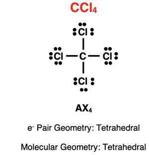
The Lewis electron dot diagram for carbon tetrachloride is shown at the right. There are four electron pairs (or electron groups) surrounding the central carbon atom. Each pair is a shared pair involved in bonding. There are no lone pairs on carbon. Its AXE notation is AX4E0 or simply AX4. With four electron pairs surrounding the central atom, the electron pair geometry is tetrahedral. With no lone pairs, the molecular geometry is also tetrahedral.
Example: PCl5
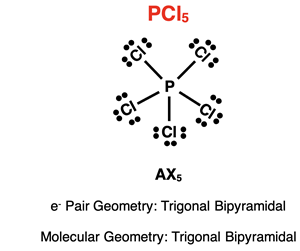 The Lewis electron dot diagram for phosphorus pentachloride is shown at the right. As discussed in Lesson 2, the phosphorus atom in PCl5 is an expanded octet that uses its d orbitals to house the additional electron pairs. There are five electron pairs (or electron groups) surrounding the central P atom. Each pair is a shared pair involved in bonding. There are no lone pairs on phosphorus. Its AXE notation is AX5E0 or simply AX5. With five electron repelling electron groups surrounding the central atom, the electron pair geometry is trigonal bipyramidal. With no lone pairs, the molecular geometry is also trigonal bipyramidal.
 Example: SF6
The Lewis electron dot diagram for sulfur hexafluoride is shown at the right. As discussed in Lesson 2, the sulfur atom in SF6 is an expanded octet that uses its d orbitals to house the additional electron pairs. There are six electron pairs (or electron groups) surrounding the central sulfur atom. Each pair is a shared pair involved in bonding. There are no lone pairs on sulfur. Its AXE notation is AX6E0 or simply AX6. With six repelling electron groups surrounding the central atom, the electron pair geometry is octahedral. With no lone pairs, the molecular geometry is also octahedral.
Visual Models
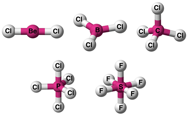
For those students who have difficulties with spatial visualization, an effective visual model can be a game-changer. Numerous graphics and representations are readily available through a Google Images search using the electron pair geometry name as a search term. The graphic below provides our version of a visual model for each of the five examples above.
Multiple Bonds
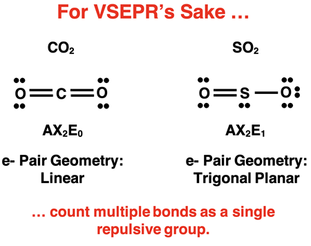
As discussed in Lesson 2, some molecules have terminal atoms that are double bonded or triple bonded to the central atom. That’s actually two pairs of electrons (double bond) and three pairs of electrons (triple) just for the bond. But do beware! For the sake of electron repulsions, a bond will act like on repelling electron group, whether it be a double bond or a triple bond. Count a multiple bond as a single repulsive group. For instance, carbon in CO2 (shown below) is considered to have a two bond pairs and no lone pairs. Its AXE notation is AX2E0 and its electron pair geometry and molecular geometry is linear. The sulfur atom in SO2 (shown below) is considered to have a two bond pairs and one lone pair. Its AXE notation is AX2E1. Its electron pair geometry trigonal planar and its molecular geometry is … (Oops. You’ll have to wait until Lesson 3b for that.).
Summarizing Molecular Geometries (No Lone Pairs)
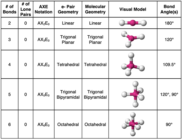
The above information is summarized in the table below. (We will add to this table in Lesson 3b.)
Methods Matter
We offer the following method for determining the electron pair geometry and the molecular geometry for a given molecule.
- Draw the Lewis electron dot diagram. (This is not optional. You will need to know how many bonds and how many lone pairs are on the central atom.)
- Analyze the central atom. Count the number of bonds and the number of lone pairs. (Count multiple bonds as one bond.)
- Sum the number of bonds and the number of lone pairs. The sum will allow you to determine the electron pair geometry.
- If there are no lone pairs, then the molecular geometry will be identical to the electron pair geometry. If there are long pairs, then you will need to continue on to our Advanced VSEPR lesson – Lesson 3b.
Special Thanks
We have made extensive use of a collection of Public Domain images found on Wikimedia Commons. A special thanks goes out to
Ben who has contributed these images to the public domain.
Before You Leave
Check Your Understanding
Use the following questions to assess your understanding. Tap the
Check Answer buttons when ready.
1. Which method best explains how to determine the AXE notation of a compound?
- Look at the formula. You can always tell the AXE notation from CH4 or NCl3 or SO3.
- Draw the electron dot diagram. Then inspect the central atom for bonds and lone pairs.
- Take a wild guess at it. It’s a lot easier. And when you get it right, it’s exhilarating.
- Get the phone number of the smartest person in the class. Give them a call. Just ask.
2.
TRUE or
FALSE:
BCl3 has an electron pair geometry that is trigonal planar. Thus, any other molecule with a similar formula – like NCl3 or even SO3 – will have the same trigonal planar electron pair geometry.
3. Under what conditions will the electron pair geometry and the molecular geometry be the same? Explain your answer.
4. The AXE notation of three molecules is shown below.
Which of the molecules have the same electron pair geometry?
- A and B
- A and C
- B and C
- None of these do
5. Consider the following electron dot diagrams. For each, identify the AXE notation and the electron pair geometry.
6. For the following molecules, draw the Lewis electron dot diagram. Identify the AXE notation. Identify the electron pair geometry and the molecular geometry.
- SO3 (skip molecular geometry)
- CO2
- CH2Cl2
- HCN (C is the central atom)