Hold down the T key for 3 seconds to activate the audio accessibility mode, at which point you can click the K key to pause and resume audio. Useful for the Check Your Understanding and See Answers.
Another Application of the Force-finding Right Hand Rule
Way back in 1820 when Oersted discovered that electricity causes magnetism, he likely had no idea how revolutionary his discovery would be. The fact that electricity and magnetism are connected—that a magnetic field exerts a force on a wire when it is carrying current—is now the physics behind hundreds of engineering marvels. We saw in the previous section of this lesson, for example, that this is the principle behind how a speaker operates. There are countless more applications of this physics principle. We’ll consider another in this section as we work to make sense of what makes an electric motor spin.
Let’s consider a rectangular loop of wire that is carrying current. Next, let’s place this wire loop in the magnetic field of a horseshoe magnet as shown in the side view below. Using the Force-finding Right Hand Rule we see that the left and right sides of the loop feel a magnetic force. You might use this rule to convince yourself that the left side would be pulled upward while the right segment would be pulled downward. The other two sides of the loop feel no force since these currents are parallel to the B-field. What is important to notice is that the upward and downward forces act on different sides of the loop that are at a distance from the axis of rotation (shown as the dotted line). This results is the loop wanting to rotate around this axis. Whenever a force acts at a distance from an axis of rotation and is perpendicular to this lever arm, the force applies a torque. Let’s understand the torque that acts on this rectangular loop.
 A rectangular loop of wire is allowed to pivot on the axis and is placed between the north and south magnetic poles of a horseshoe magnet. The magnetic field flows from north to south, and the current flows 'out of' the page on the left from the side view, and into the page on the right from the side view. This results in a upwards force on the left, and downards on the right. The text reads "Using the Force-finding right hand rule, the left and right sides of the rectangular current loop feel a force out of the page and into the page respectively. If the loop is mounted on an axis as shown, the loop will rotate.
Finding Torque
In our future chapter on rotational motion, we will described torque as the effectiveness of a force to produce rotation. Forces can produce rotation when (1) they act at a distance (the lever arm) from a pivot or axis of rotation, and (2) the force acts perpendicular to this lever arm. By analyzing the current-carrying loop that is in the horseshoe magnet’s B-field, we see that this is exactly the case. In other words, this wire loop has a torque applied to both the left- and right-side wires since they each experience a magnetic force and since these forces act perpendicular to a lever arm measured from the axis of rotation. Applying the net torque equation that will be learned in our rotational motion unit, we will be able to derive an expression for the torque. We see that this torque depends on the number of loops of wire, the current in the wire, the area of the loop, and the strength and direction of the magnetic field.
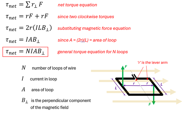
We start with T net = the Sum of the perpendicular radius (radius of lever arm) times Force.
Since there are 2 clockwise torques, the Sum becomes the radius times force + radius times force, or 2 r F.
Substitute Force for I L B (magnetic force equation), we get net torque = 2 r times I L B.
Since the area of the loop is 2 times the radius ('width') times the length , we replace 2 r L with A for area.
Lastly, since we may have multiple loops that will amplify this all, net torque = Number of loops (N) times Current (I) times Area of the loop (A) times the Perpendicular magnetic field (B perpendicular).
The magnetic field in this equation has a perpendicular sign in the subscript. You might wonder, “What is the magnetic field perpendicular to?” The answer lies in our defining a new type of vector—an area vector. Up to this point, we have never thought of an area being a vector--but here is a place where it is actually helpful to do so. Like all vectors, an area vector has a magnitude and direction. Its magnitude is simply the area outlined by the loop of wire. In the case of our rectangular loop, this would simply be A = (2r) (L). The direction of our area vector is defined as being perpendicular to this surface area itself, as shown in this figure.
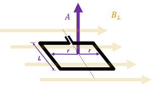
We can see that the orientation of our loop is such that the B-field is indeed perpendicular to the area vector. When the magnetic field is perpendicular to the area vector, we are in the orientation where the loop of wire will experience the maximum torque. For the loop shown here, this torque will cause the loop to rotate clockwise.
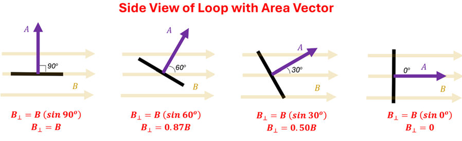
You’ll notice that once the loop starts to rotate the area vector rotates along with it. While its magnitude stays the same, its direction changes. In our example, since the angle between the area vector and the magnetic field gets smaller and smaller, the torque (the effectiveness of the magnetic force to produce a rotation) decreases. Said another way, as the perpendicular component of the B-field decreases, the torque decreases.
Example 1: Predicting the Direction of Rotation
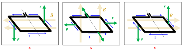
Problem: For each of the situations below, determine if the magnetic forces on the loop will produce a clockwise rotation, a counterclockwise rotation, or no rotation about the dotted axis shown.
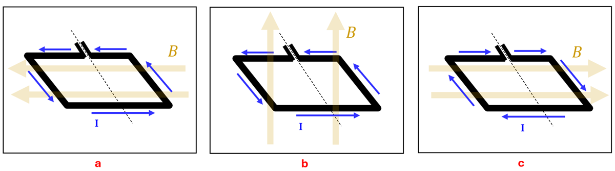
Solution: (a) Counterclockwise rotation. Using the Force-finding Right Hand Rule, we see that the left and right sides of the loop with feel a force downward and upward respectively. Since these forces are perpendicular to the lever arm (the radial vector from the axis of rotation to the place where the force acts), they will exert a counterclockwise torque. (b) No rotation. While each side of the loop will experience a force, none of these forces will cause a rotation around the axis. (c) Counterclockwise rotation. Here the left segment of wire feels a magnetic force downward and the right segment feels a force upward. Thus, these forces will create a torque causing the loop to rotate counterclockwise.
Example 2: Calculating Torque
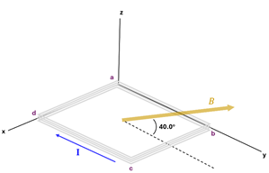
Problem: A rectangular loop consists of three closely wrapped turns of wire as shown in the figure. Its dimensions are a = 0.20 m and b = 0.15 m. The loop is hinged along the y-axis, and its plane makes an angle of 30o with the x-axis.
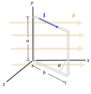
(a) What is the magnitude of the torque acting on the loop of a magnetic field of 0.50 T is directed on the +x direction and the current of the loop is 2.5 A in the direction shown?
(b): If you are looking down along the +y-axis, what is the expected direction of the rotation?
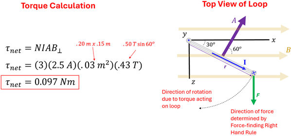
Solution: (a) Using the torque equation derived above, we find the net torque to be 0.097 Nm (τnet = (3)(2.5 A)(0.2 m * .15 m)(0.5 T * sin(60))). Recall that when finding the component of the magnetic field perpendicular to the area vector, we multiply the strength of the magnetic field by the sine of the angle between the area vector and the field. We can see from the drawing below that this angle is 60o. (b) To find the direction of force on the vertical segment of the loop furthest from y-axis, we apply the Force-finding Right Hand Rule to see that the force will point toward in the +z direction. We can ignore the force acting on the vertical segment along the y-axis as this force will not exert a torque since this force acts at the location of the pivot. We can also ignore the magnetic forces acting on the top and bottom segments since these forces (which point in the +y and -y directions respectively) will cancel out. Finally, then, to predict the direction of rotation, we see that the force on the vertical segment furthest from the y-axis is applied in such a way that it will cause the loop to rotate clockwise—toward the +z-axis.
What is Missing that Keeps a Motor Spinning
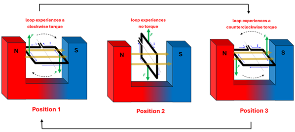
We’ve learned above that when the area vector of a current-carry loop is perpendicular to the magnetic field, a torque will cause the loop to rotate (Position 1). We also saw that once the loop rotates a quarter turn (such that the area vector now points parallel to the magnetic field) there is no longer a torque acting on the loop (Position 2). It is also true that the angular momentum of the loop itself will cause it to continue to rotate beyond a quarter turn—but what happens then? Beyond a quarter turn (let’s say at half a turn) the loop will now experience a torque in the opposite direction (Position 3). This is because the current is now pointing in the opposite direction since the loop has turned upside down. The result is that the loop will wobble from Positions 1 to 2 to 3…then from 3 to 2 to 1…and then repeat this process. Because of friction, the loop will eventually stop in Position 2. In other words, we’ve created a loop that wobbles but doesn’t continue to spin.
So how do we get a motor to continue to spin in one direction? A clever engineer designed a device called a commutator. A commutator is simply two semi-circular metal arcs that are connected to the two ends of the spinning loop. Because a different arc makes contact with the wire that is connected to the positive terminal of the battery every half turn, the current flips directions every half turn. The result is that current is always pointing in the same direction every time a portion of the loop gets to a given position. Thus, the motor will continue to spin in one direction!
Figure 1
Now that our motor keeps spinning in the same direction, we can connect a fan blade to the spinning loop and make the ceiling fan in your bedroom…or a propeller on an aircraft…or a motor that runs a thousand different devices that you will use over the course of the year.
Throughout this chapter we have explored a few basic principles that connect electricity and magnetism. You can see that uncovering these physics principles allows us to understand how everyday devices actually work. That’s pretty neat. The exciting thing is that, while this lesson is complete, we have yet to explore a whole new connection between electricity and magnetism in the next chapter—electromagnetic induction. It is here that we’ll uncover the physics behind wireless charging of cell phones, regenerative braking in hybrid cars, and how the electricity delivered to your home is generated in the first place. Join us in the next chapter and we’ll learn about these engineering marvels and much more.
Check Your Understanding
Use the following questions to assess your understanding. Tap the Check Answer buttons when ready.
1. A horseshoe magnet creates a uniform magnetic field of 0.50 T between its poles. A single rectangular loop of wire between the poles has dimensions a = 8.0 cm and b = 6.0 cm. The current in the loop is 4.0 A. At a given moment, the side view shows the loop’s orientation making an angle of 75o from the horizontal.
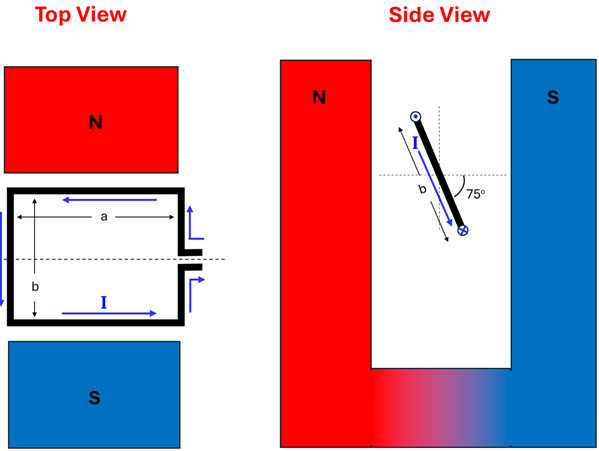
Using the top view,
(A) What is the direction of the magnetic field?
(B) What is the direction of the force on the top segment of wire?
(C) What is the direction of the force on the bottom segment of wire?
Using the side view,
(D) What is the direction of the magnetic field?
(E) What is the direction of the force on the top segment of wire that is carrying current out of the page?
(F) What is the direction of the force on the bottom segment of wire that is carrying current into the page?
(G) Predict the direction the loop will rotate in ths orientation.
(H) What direction does the area vector point?
(I) What is the angle between the area vector and the direction of the magnetic field?
Using both views,
(J) Calculate the Magnitude of the toraue on the loop.
2. Four wraps of wire are made to form the rectangular loop that is hinged along the x-axis. Wire segment ab = 0.60 m and wire segment bc = 0.45 m. The wires carry a 2.0 A current. A 0.80 T magnetic field points in the direction shown.
(A) Predict the direction the loop will rotate?
(B) Calculate the magnitude of the torque that causes this rotation.
Figure 1 Source: https://commons.wikimedia.org/wiki/File:Ejs_Open_Source_Direct_Current_Electrical_Motor_Model_Java_Applet_(_DC_Motor_)_50_degree_split_ring.gif