Hold down the T key for 3 seconds to activate the audio accessibility mode, at which point you can click the K key to pause and resume audio. Useful for the Check Your Understanding and See Answers.
 As mentioned in the previous section of Lesson 4, two or more electrical devices in a circuit can be connected by series connections or by parallel connections. When all the devices are connected using series connections, the circuit is referred to as a series circuit. In a series circuit, each device is connected in a manner such that there is only one pathway by which charge can traverse the external circuit. Each charge passing through the loop of the external circuit will pass through each resistor in consecutive fashion.
 A short comparison and contrast between series and parallel circuits was made in the previous section of Lesson 4. In that section, it was emphasized that the act of adding more resistors to a series circuit results in the rather expected result of having more overall resistance. Since there is only one pathway through the circuit, every charge encounters the resistance of every device; so adding more devices results in more overall resistance. This increased resistance serves to reduce the rate at which charge flows (also known as the current).
Equivalent Resistance and Current
Charge flows together through the external circuit at a rate that is everywhere the same. The current is no greater at one location as it is at another location. The actual amount of current varies inversely with the amount of overall resistance. There is a clear relationship between the resistance of the individual resistors and the overall resistance of the collection of resistors. As far as the battery that is pumping the charge is concerned, the presence of two 6-Ω ;resistors in series would be equivalent to having one 12-Ω resistor in the circuit. The presence of three 6-Ω resistors in series would be equivalent to having one 18-Ω resistor in the circuit. And the presence of four 6-Ω resistors in series would be equivalent to having one 24-Ω resistor in the circuit.
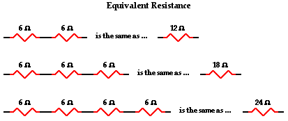
This is the concept of equivalent resistance. The equivalent resistance of a circuit is the amount of resistance that a single resistor would need in order to equal the overall effect of the collection of resistors that are present in the circuit. For series circuits, the mathematical formula for computing the equivalent resistance (Req) is
Req = R1 + R2 + R3 + ...
where R1, R2, and R3 are the resistance values of the individual resistors that are connected in series.
Make, solve and check your own problems by using the Equivalent Resistance widget below. Make yourself a problem with any number of resistors and any values. Solve the problem; then click on the Submit button to check your answer.
The current in a series circuit is everywhere the same. Charge does NOT pile up and begin to accumulate at any given location such that the current at one location is more than at other locations. Charge does NOT become used up by resistors such that there is less of it at one location compared to another. The charges can be thought of as marching together through the wires of an electric circuit, everywhere marching at the same rate. Current - the rate at which charge flows - is everywhere the same. It is the same at the first resistor as it is at the last resistor as it is in the battery. Mathematically, one might write
Ibattery = I1 = I2 = I3 = ...
where I1, I2, and I3 are the current values at the individual resistor locations.
These current values are easily calculated if the battery voltage is known and the individual resistance values are known. Using the individual resistor values and the equation above, the equivalent resistance can be calculated. And using Ohm's law (ΔV = I • R), the current in the battery and thus through every resistor can be determined by finding the ratio of the battery voltage and the equivalent resistance.
Ibattery = I1 = I2 = I3 = ΔVbattery / Req
Electric Potential Difference and Voltage Drops
As discussed in Lesson 1, the electrochemical cell of a circuit supplies energy to the charge to move it through the cell and to establish an electric potential difference across the two ends of the external circuit. A 1.5-volt cell will establish an electric potential difference across the external circuit of 1.5 volts. This is to say that the electric potential at the positive terminal is 1.5 volts greater than at the negative terminal. As charge moves through the external circuit, it encounters a loss of 1.5 volts of electric potential. This loss in electric potential is referred to as a voltage drop. It occurs as the electrical energy of the charge is transformed to other forms of energy (thermal, light, mechanical, etc.) within the resistors or loads. If an electric circuit powered by a 1.5-volt cell is equipped with more than one resistor, then the cumulative loss of electric potential is 1.5 volts. There is a voltage drop for each resistor, but the sum of these voltage drops is 1.5 volts - the same as the voltage rating of the power supply. This concept can be expressed mathematically by the following equation:
ΔVbattery = ΔV1 + ΔV2 + ΔV3 + ...
 To illustrate this mathematical principle in action, consider the two circuits shown below in Diagrams A and B. Suppose that you were to asked to determine the two unknown values of the electric potential difference across the light bulbs in each circuit. To determine their values, you would have to use the equation above. The battery is depicted by its customary schematic symbol and its voltage is listed next to it. Determine the voltage drop for the two light bulbs and then click the Check Answers button to see if you are correct.

Earlier in Lesson 1, the use of an electric potential diagram was discussed. An electric potential diagram is a conceptual tool for representing the electric potential difference between several points on an electric circuit. Consider the circuit diagram below and its corresponding electric potential diagram.
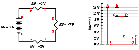
The circuit shown in the diagram above is powered by a 12-volt energy source. There are three resistors in the circuit connected in series, each having its own voltage drop. The negative sign for the electric potential difference simply denotes that there is a loss in electric potential when passing through the resistor. Conventional current is directed through the external circuit from the positive terminal to the negative terminal. Since the schematic symbol for a voltage source uses a long bar to represent the positive terminal, location A in the diagram is at the positive terminal or the high potential terminal. Location A is at 12 volts of electric potential and location H (the negative terminal) is at 0 volts. In passing through the battery, the charge gains 12 volts of electric potential. And in passing through the external circuit, the charge loses 12 volts of electric potential as depicted by the electric potential diagram shown to the right of the schematic diagram. This 12 volts of 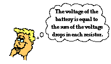 electric potential is lost in three steps with each step corresponding to the flow through a resistor. In passing through the connecting wires between resistors, there is little loss in electric potential due to the fact that a wire offers relatively little resistance to the flow of charge. Since locations A and B are separated by a wire, they are at virtually the same electric potential of 12 V. When a charge passes through its first resistor, it loses 3 V of electric potential and drops down to 9 V at location C. Since location D is separated from location C by a mere wire, it is at virtually the same 9 V electric potential as C. When a charge passes through its second resistor, it loses 7 V of electric potential and drops down to 2 V at location E. Since location F is separated from location E by a mere wire, it is at virtually the same 2 V electric potential as E. Finally, as a charge passes through its last resistor, it loses 2 V of electric potential and drops down to 0 V at G. At locations G and H, the charge is out of energy and needs an energy boost in order to traverse the external circuit again. The energy boost is provided by the battery as the charge is moved from H to A.
In Lesson 3, Ohm's law (ΔV = I • R) was introduced as an equation that relates the voltage drop across a resistor to the resistance of the resistor and the current at the resistor. The Ohm's law equation can be used for any individual resistor in a series circuit. When combining Ohm's law with some of the principles already discussed on this page, a big idea emerges. 
In series circuits, the resistor with the greatest resistance has the greatest voltage drop.
Since the current is everywhere the same within a series circuit, the I value of ΔV = I • R is the same in each of the resistors of a series circuit. So the voltage drop (ΔV) will vary with varying resistance. Wherever the resistance is greatest, the voltage drop will be greatest about that resistor. The Ohm's law equation can be used to not only predict that resistor in a series circuit will have the greatest voltage drop, it can also be used to calculate the actual voltage drop values.
|
ΔV1 = I • R1
|
ΔV2 = I • R2
|
ΔV3 = I • R3
|
Mathematical Analysis of Series Circuits
.png?width=198&height=130) The above principles and formulae can be used to analyze a series circuit and determine the values of the current at and electric potential difference across each of the resistors in a series circuit. Their use will be demonstrated by the mathematical analysis of the circuit shown below. The goal is to use the formulae to determine the equivalent resistance of the circuit (Req), the current at the battery (Itot), and the voltage drops and current for each of the three resistors.
The above principles and formulae can be used to analyze a series circuit and determine the values of the current at and electric potential difference across each of the resistors in a series circuit. Their use will be demonstrated by the mathematical analysis of the circuit shown below. The goal is to use the formulae to determine the equivalent resistance of the circuit (Req), the current at the battery (Itot), and the voltage drops and current for each of the three resistors.

The analysis begins by using the resistance values for the individual resistors in order to determine the equivalent resistance of the circuit.
Req = R1 + R2 + R3 = 17 Ω + 12 Ω + 11 Ω = 40 Ω
Now that the equivalent resistance is known, the current at the battery can be determined using the Ohm's law equation. In using the Ohm's law equation (ΔV = I • R) to determine the current in the circuit, it is important to use the battery voltage for ΔV and the equivalent resistance for R. The calculation is shown here:
Itot = ΔVbattery / Req = (60 V) / (40 Ω) = 1.5 amp
The 1.5 amp value for current is the current at the battery location. For a series circuit with no branching locations, the current is everywhere the same. The current at the battery location is the same as the current at each resistor location. Subsequently, the 1.5 amp is the value of I1, I2, and I3.
Ibattery = I1 = I2 = I3 = 1.5 amp
There are three values left to be determined - the voltage drops across each of the individual resistors. Ohm's law is used once more to determine the voltage drops for each resistor - it is simply the product of the current at each resistor (calculated above as 1.5 amp) and the resistance of each resistor (given in the problem statement). The calculations are shown below.
|
ΔV1 = I1 • R1
ΔV1 = (1.5 A) • (17 Ω)
ΔV1 = 25.5 V
|
ΔV2 = I2 • R2
ΔV2 = (1.5 A) • (12 Ω)
ΔV2 = 18 V
|
ΔV3 = I3 • R3
ΔV3 = (1.5 A) • (11 Ω)
ΔV3 = 16.5 V
|
As a check of the accuracy of the mathematics performed, it is wise to see if the calculated values satisfy the principle that the sum of the voltage drops for each individual resistor is equal to the voltage rating of the battery. In other words, is ΔVbattery = ΔV1 + ΔV2 + ΔV3 ?
Is ΔVbattery = ΔV1 + ΔV2 + ΔV3 ?
Is 60 V = 25.5 V + 18 V + 16.5 V ?
Is 60 V = 60 V?
Yes!!
The mathematical analysis of this series circuit involved a blend of concepts and equations. As is often the case in physics, the divorcing of concepts from equations when embarking on the solution to a physics problem is a dangerous act. Here, one must consider the concepts that the current is everywhere the same and that the battery voltage is equivalent to the sum of the voltage drops across each resistor in order to complete the mathematical analysis. In the next part of Lesson 4, parallel circuits will be analyzed using Ohm's law and parallel circuit concepts. We will see that the approach of blending the concepts with the equations will be equally important to that analysis.
We Would Like to Suggest ...

Why just read about it and when you could be interacting with it? Interact - that's exactly what you do when you use one of The Physics Classroom's Interactives. We would like to suggest that you combine the reading of this page with the use of our
DC Circuit Builder Interactive. You can find it in the Physics Interactives section of our website. The
DC Circuit Builder provides the learner with a virtual circuit building kit. You can easily drag voltage sources, resistors and wires onto the workspace and arrange and connect them anyway you wish. Voltmeters and ammeters allow you to measure current and voltage drops. Tapping a resistor or a voltage source allows you to change the resistance or the input voltage. It's easy. It's fun. And it's safe (unless you're using it in the bathtub).
Check Your Understanding
1. Use your understanding of equivalent resistance to complete the following statements:
a. Two 3-Ω resistors placed in series would provide a resistance that is equivalent to one _____-Ω resistor.
b. Three 3-Ω resistors placed in series would provide a resistance that is equivalent to one _____-Ω resistor.
c. Three 5-Ω resistors placed in series would provide a resistance that is equivalent to one _____-Ω resistor.
d. Three resistors with resistance values of 2-Ω , 4-Ω , and 6-Ω are placed in series. These would provide a resistance that is equivalent to one _____-Ω resistor.
e. Three resistors with resistance values of 5-Ω , 6-Ω , and 7-Ω are placed in series. These would provide a resistance that is equivalent to one _____-Ω resistor.
f. Three resistors with resistance values of 12-Ω, 3-Ω, and 21-Ω are placed in series. These would provide a resistance that is equivalent to one _____-Ω resistor.
2. As the number of resistors in a series circuit increases, the overall resistance __________ (increases, decreases, remains the same) and the current in the circuit __________ (increases, decreases, remains the same).
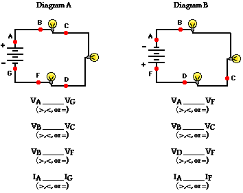
3. Consider the following two diagrams of series circuits. For each diagram, use arrows to indicate the direction of the conventional current. Then, make comparisons of the voltage and the current at the designated points for each diagram.
 4. Three identical light bulbs are connected to a D-cell as shown at the right. Which one of the following statements is true?
a. All three bulbs will have the same brightness.
b. The bulb between X and Y will be the brightest.
c. The bulb between Y and Z will be the brightest.
d. The bulb between Z and the battery will be the brightest.
 5. Three identical light bulbs are connected to a battery as shown at the right. Which adjustments could be made to the circuit that would increase the current being measured at X? List all that apply.
a. Increase the resistance of one of the bulbs.
b. Increase the resistance of two of the bulbs.
c. Decrease the resistance of two of the bulbs.
d. Increase the voltage of the battery.
e. Decrease the voltage of the battery.
f. Remove one of the bulbs.
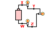 6. Three identical light bulbs are connected to a battery as shown at the right. W, X,Y and Z represent locations along the circuit. Which one of the following statements is true?
a. The potential difference between X and Y is greater than that between Y and Z.
b. The potential difference between X and Y is greater than that between Y and W.
c. The potential difference between Y and Z is greater than that between Y and W.
d. The potential difference between X and Z is greater than that between Z and W.
e. The potential difference between X and W is greater than that across the battery.
f. The potential difference between X and Y is greater than that between Z and W.
 7. Compare circuit X and Y below. Each is powered by a 12-volt battery. The voltage drop across the 12-ohm resistor in circuit Y is ____ the voltage drop across the single resistor in X.
a. smaller than
b. larger than
c. the same as
 8. A 12-V battery, a 12-ohm resistor and a light bulb are connected as shown in circuit X below. A 6-ohm resistor is added to the 12-ohm resistor and bulb to create circuit Y as shown. The bulb will appear ____.
a. dimmer in circuit X
b. dimmer in circuit Y
c. the same brightness in both circuits
9. Three resistors are connected in series. If placed in a circuit with a 12-volt power supply. Determine the equivalent resistance, the total circuit current, and the voltage drop across and current at each resistor.
