Electricity: Electric Circuits
Electric Circuits: Problem Set Overview
There are 15 ready-to-use problem sets on the topic of Electric Circuits. The problems target your ability to use circuit concepts and equations to analyze simple circuits, series circuits, parallel circuits, and combination circuits. Problems range in difficulty from the very easy and straight-forward to the very difficult and complex.
Current
When charge flows through the wires of an electric circuit, current is said to exist in the wires. Electric current is a quantifiable notion that is defined as the rate at which charge flows past a point on the circuit. It can be determined by measuring the quantity of charge that flows past a cross-sectional area of a wire on the circuit. As a rate quantity, current (I) is expressed by the following equation
I = Q / t
where Q is the quantity of charge flowing by a point in a time period of t. The standard metric unit for the quantity current is the ampere, often abbreviated as Amps or A. A current of 1 ampere is equivalent to 1 Coulomb of charge flowing past a point in 1 second. Since the quantity of charge passing a point on a circuit is related to the number of mobile charge carriers (electrons) which flow past that point, the current can also be related to the number of electrons and the time. To make this connection between the current and the number of electrons, one must know the quantity of charge on a single electron.
Qelectron = 1.6 x 10⁻¹⁹ C
Resistance
As charge flows through a circuit, it encounters resistance or a hindrance to its flow. Like current, resistance is a quantifiable term. The quantity of resistance offered by a section of wire depends upon three variables - the material the wire is made out of, the length of the wire, and the cross-sectional area of the wire. One physical property of a material is its resistivity - a measure of that material's tendency to resist charge flow through it. Resistivity values for various conducting materials are typically listed in textbooks and reference books. Knowing the resistivity value (ρ) of the material the wire is composed of and its length (L) and cross-sectional area (A), its resistance (R) can be determine using the equation below.
R = ρ • L / A
The standard metric unit of resistance is the ohm (abbreviated by the Greek letter Ω).
The main difficulty with the use of the above equation pertains to the units of expression of the various quantities. The resistivity (ρ) is typically expressed in ohm•m. Thus, the length should be expressed in units of m and the cross-sectional area in m2. Many wires are round and have a circular cross-section. As such, the cross-sectional area in the above equation can be calculated from knowledge of the wire's radius or diameter using the formula for the area of a circle.
A = π • R2 = π • D2 / 4
Use our video on Electric Resistance fo solidfy your understanding of these resistance formulas.
Voltage-Current-Resistance Relationship
The amount of current that flows in a circuit is dependent upon two variables. Current is inversely proportional to the overall resistance (R) of the circuit and directly proportional to the electric potential difference impressed across the circuit. The electric potential difference (ΔV) impressed across a circuit is simply the voltage supplied by the energy source (batteries, outlets, etc.). For homes in the United States, this value is close to 110-120 Volts. The mathematical relationship between current (I), voltage and resistance is expressed by the following equation (which is sometimes referred to as the Ohm's law equation).
ΔV = I • R
Power
Electrical circuits are all about energy. Energy is put into a circuit by the battery or the commercial electricity supplier. The elements of the circuit (lights, heaters, motors, refrigerators, and even wires) convert this electric potential energy into other forms of energy such as light energy, sound energy, thermal energy and mechanical energy. Power refers to the rate at which energy is supplied or converted by the appliance or circuit. It is the rate at which energy is lost or gained at any given location within the circuit. As such, the generic equation for power is
P = ΔE / t
The energy loss (or gain) is simply the product of the electric potential difference between two points and the quantity of charge which moves between those two points in a time period of t. As such, the energy loss (or gain) is simply ΔV • Q. When this expression is substituted into the above equation, the power equation becomes
P = ΔV • Q / t
Since the Q/t ratio found in the above equation is equal to the current (I), the above equation can also be written as
P = ΔV • I
By combining the Ohm's law equation with the above equation, two other power equations can be generated. They are
The standard metric unit of power is the Watt. In terms of units, the Watt is equivalent to an Amp•Volt, an Amp2•Ohm, and a Volt2/Ohm.
Our video on Electric Power Equations will discuss these formulae in greater detail.
Electricity Costs
A commercial power company charges households for the energy supplied on a monthly basis. The bill for the services typically states the amount of energy consumed during the month in units of kiloWatt•hours. This unit - a power unit multiplied by a time unit - is a unit of energy. A household typically pays the bill on the basis of the number of kW•hr of electrical energy consumed during the month. Thus, the task of determining the cost of using a specific appliance for a specified period of time is quite straightforward. The power must first be determined and converted to kiloWatts. This power must then be multiplied by the usage time in hours to obtain the energy consumed in units of kW•hr. Finally, this energy amount must be multiplied by the cost of electricity on a $/kW•hr basis in order to determine the cost in dollars.
Equivalent Resistance
It is quite common that a circuit consist of more than one resistor. While each resistor has its own individual resistance value, the overall resistance of the circuit is different than the resistance of the individual resistors which make up the circuit. A quantity known as the equivalent resistance indicates the total resistance of the circuit. Conceptually, the equivalent resistance is the resistance that a single resistor would have in order to produce the same overall effect on the resistance as the combination of resistors that are present. So if a circuit has three resistors with an equivalent resistance of 25 ohm, then a single 25-ohm resistor could replace the three individual resistors and have the equivalent effect upon the circuit. The value of the equivalent resistance (Req) takes into consideration the individual resistance values of the resistors and the way in which those resistors are connected.
There are two basic ways in which resistors can be connected in an electrical circuit. They can be connected in series or in parallel. Resistors that are connected in series are connected in consecutive fashion such that all the charge that passes through the first resistor will also pass through the other resistors. In series connection, all of the charge flowing through the circuit passes through each one of the individual resistors. As such, the equivalent resistance of series-connected resistors is the sum of the individual resistance values of those resistors.
Req = R1 + R2 + R3 + … (series connections)
Resistors that are connected in parallel are connected in side-by-side fashion such that the charge approaching the resistors will split up into two or more different paths. Parallel-connected resistors are characterized as having branching locations where charge branches off into the different pathways. The charge which passes through one resistor will not pass through the other resistors. The equivalent resistance of parallel-connected resistors is less than the resistance values of all the individual resistors in the circuit. While it may not be entirely intuitive, the equation for the equivalent resistance of parallel-connected resistors is given by an equation with several reciprocal terms.
1/Req = 1/R1 + 1/R2 + 1/R3 + … (parallel connections)
Series Circuit Analysis
Several of the problems in this unit pertain to series circuits. It is not unusual that a problem be accompanied by a drawing or a schematic diagram showing the arrangement of batteries and resistors. The drawing and corresponding schematic diagram below represents a series circuit powered by three cells and having three series-connected resistors (light bulbs).
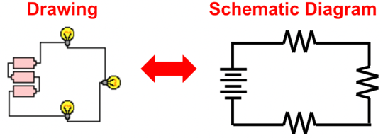
By imagining a charge leaving the positive terminal of the battery and following its path as it traverses the complete loop, it becomes evident that the charge goes through every resistor in consecutive fashion. As such it meets the criteria of a series circuit. Knowing that the circuit is a series circuit, allows you to relate the overall or equivalent resistance of the circuit to the individual resistance values by the equivalent resistance equation discussed above.
Req = R1 + R2 + R3 + … (series connections)
The current of a series circuit is the same in the resistors as it is in the battery. Since there is no branching off locations where charge divides into pathways, it can be stated that the current in the battery is equal to the current in resistor 1 is equal to the current in resistor 2 and is equal to the current in resistor 3 ... . In equation form, it can be written that
Ibattery = I1 = I2 = I3 = … (series circuits)
As charge traverses the resistors of a series circuit, there is a drop in electric potential as it passes through each resistor. This drop in electric potential across each resistor is determined by the current through the resistor and the resistance of the resistor. This is consistent with the Ohm's law equation described above (ΔV = I • R). Since the current (I) in each individual resistor is the same, it is logical to conclude that the resistors with the greatest resistance (R) will have the greatest electric potential difference (ΔV) impressed across them.
The electric potential difference across the individual resistors of a circuit is often referred to as a voltage drop. These voltage drops of the series-connected resistors are mathematically related to the electric potential or voltage rating of the cells or battery which power the circuit. If a charge gains 12 volts of electric potential as it passes through the battery of an electric circuit, then it will lose 12 V as it passes through the external circuit. This 12 V drop in electric potential results from a series of individual drops in electric potential as it passes through the individual resistors of the series circuit. These individual voltage drops (electric potential difference) add up to give the total voltage drop of the circuit, In equation form, It can be said that
ΔVbattery = ΔV1 + ΔV2 + ΔV3 + … (series circuits)
where ΔVbattery is the electric potential gained in the battery and ΔV1, ΔV2 and ΔV3 are the voltage drops (or electric potential differences) across the individual resistors.
A more detailed and exhaustive discussion of series circuits and their analysis can be found at The Physics Classroom Tutorial. And our videos on Series Circuit Relationships and Series Circuit Analysis will be very helpful.
Parallel Circuit Analysis
Several problems in this unit pertain to parallel circuits. Again, it is not unusual that a problem be accompanied by a drawing or a schematic diagram showing the arrangement of batteries and resistors. The drawing and corresponding schematic diagram below represents a parallel circuit powered by three cells and having three parallel-connected resistors (light bulbs).
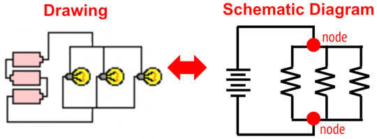
By imagining a charge leaving the positive terminal of the battery and following its path as it traverses the complete loop, it becomes evident that the charge reaches a branching location (a node) prior to reaching a resistor. At the branching location sometimes referred to as a node, charge follows one of the three possible paths through the resistors. Rather than pass through every resistor, a single charge will pass through a single resistor during a complete loop around the circuit. As such it meets the criteria of a parallel circuit. Knowing that the circuit is a parallel circuit, allows you to relate the overall or equivalent resistance of the circuit to the individual resistance values by the equivalent resistance equation discussed above.
1/Req = 1/R1 + 1/R2 + 1/R3 + … (parallel connections)
At the branching location, charge is splitting into separate pathways. As such, the current in the individual pathways will be less than the current outside the pathways. The overall current flow in the circuit and the current in the battery is equal to the sum of the current in the individual pathways. In equation form, it can be written that
Ibattery = I1 + I2 + I3 + … (parallel circuits)
The current values of these individual branches are controlled by two quantities - the resistance of the resistor in the branch and the electric potential difference (ΔV) impressed across the branch. Consistent with Ohm's law equation discussed above, it can be said that the current in branch 1 is equal to the electric potential difference across branch 1 divided by the resistance of branch 1. Similar statements can be made of the other branches. In equation form, it can be stated that
| I1= ΔV1 / R1 |
I2= ΔV2 / R2 |
I3= ΔV3 / R3 |
The electic potential differences (ΔV1, ΔV2 and ΔV3) across the individual resistors are often referred to as voltage drops. Similar to series circuits, any charge leaving the battery must encounter the same drop in voltage as the gain that it encounters when passing through the battery. But unlike series circuits, a charge in a parallel circuit will only pass through one resistor. As such, the voltage drop across that resistor must equal the electric potential difference across the battery. In equation form, it can be stated that
ΔVbattery = ΔV1 = ΔV2 = ΔV3 + … (parallel circuits)
where ΔVbattery is the electric potential gained in the battery and ΔV1, ΔV2 and ΔV3 are the voltage drops (or electric potential differences) across the individual resistors.
A more detailed and exhaustive discussion of parallel circuits and their analysis can be found at The Physics Classroom Tutorial. And our videos on Parallel Circuit Relationships and Parallel Circuit Analysis will be very helpful.
Habits of an Effective Problem-Solver
An effective problem solver by habit approaches a physics problem in a manner that reflects a collection of disciplined habits. While not every effective problem solver employs the same approach, they all have habits which they share in common. These habits are described briefly here. An effective problem-solver...
- ...reads the problem carefully and develops a mental picture of the physical situation. If needed, they sketch a simple diagram of the physical situation to help visualize it.
- ...identifies the known and unknown quantities and records them in an organized manner, often times recording them on the diagram itself. They equate given values to the symbols used to represent the corresponding quantity (e.g., ΔV = 9.0 V; R = 0.025 Ω; I = ???).
- ...plots a strategy for solving for the unknown quantity; the strategy will typically center around the use of physics equations and be heavily dependent upon an understanding of physics principles.
- ...identifies the appropriate formula(s) to use, often times writing them down. Where needed, they perform the needed conversion of quantities into the proper unit.
- ...performs substitutions and algebraic manipulations in order to solve for the unknown quantity.
Read more...
Additional Readings/Study Aids:
The following pages from The Physics Classroom Tutorial may serve to be useful in assisting you in the understanding of the concepts and mathematics associated with these problems.
Watch a Video
We have developed and continue to develop Video Tutorials on introductory physics topics. You can find these videos on our YouTube channel. We have an entire Playlist on the topic of Electric Circuits.